#WDM transponder
Explore tagged Tumblr posts
Visit Tumblr Blog
Explore Tumblr blogs with no restrictions, modern design and the best experience.
Last Seen Tumblr Blogs


Fun Fact
130K people were victims of a chain letter scam that affected Tumblr in May 2011.
Text
Economical Solutions for 10G to 40G Connection
With the accelerated development of optical network, there exist more and more capacity-hungry applications in 10G networks today. To solve this problem, experts put forward the 10G to 40G connection as an ideal solution. However, due to the high migration cost, we are prevented from making the migration. Do you also meet this issue? In this paper, it will offer several solutions for making 10G to 40G connections with less cost. Hope you can find one that suits your network.

Economical Solutions for 10G to 40G Short Connection
How to make a short link between 10G and 40G switches? You can choose the 40GBASE-SR4 QSFP+ module that supports the 40G network at length up to 150 m. Meanwhile, four 10GBASE-SR SFP+ modules are required. So is the MTP-LC harness cable for connecting QSFP+ and four SFP+ modules. In details, FS.COM offers OM3 MTP-LC harness cable supporting 40G connection up to 100 m and OM4 up to150 m. All these equipment mentioned above are available at FS.COM with good prices. For the details, you can learn from the following table.

If the link distance is longer than 150 m in your network, 40GBASE-CSR4 QSFP+ module may be a better choice. It can transmit the 40G signals longer, up to 400 m. As for the fiber patch cable, you can still chosse OM3 or OM4 MTP-LC harness cable. In general, the OM3 provided by FS.COM enables the connection up to 300 m, while OM4 up to 400 m. When making a short 10G to 40G migration, you can just choose FS.COM as an ideal fiber optical manufacturer. It offers all the equipment your network needs, including 10G and 40G switches, SFP+ and QSFP+ module and MTP-LC patch cable.
Economical Solutions for 10G to 40G Long Connection
Do you need to make a long 10G to 40G migration? FS.COM also offers several cost effective solutions. For example, up to 1km, 10km, 40km or even 80km 10G to 40G connection solutions. Let’s talk about the detail information of these solutions.
Spending Less for up to 40km 10G to 40G Connection
You can use the 40GBASE-PLRL4 QSFP+ and 10GBASE-LR SFP+ modules to support the 10G to 40G migration up to 1 km. The 40GBASE-LRL4 QSFP+ is also a good choice. As for the fiber patch cable, you can choose the 8 fibers single mode MTP-LC harness cable. Once the distance is longer than 1 km, your are suggested to use the 40GBASE-LR4 QSFP+ and 40GBASE-PLR4 QSFP+ modules. These two kinds of fiber transceiver modules enable the connection at lengths up to 10 km. It the link distance is up to 40 km, then you can use the 40GBASE-ER4 QSFP+ module. Here are the related equipment offered by FS.COM.

Spending Less for up to 80km 10G to 40G Connection
Have you ever felt puzzled about whether the 10G to 40G connection can be extended to 80 km? Here you’ll find the answer is yes. How to deploy 80km 10G to 40G connection? You should add the extra equipment, including two DWDM Mux Demux, two WDM transponder OEO (Optical-Electrical-Optical) repeaters and several DWDM SFP+ modules, to your network.
In order to make a smooth 80km 10G to 40G migration, we should add the WDM transponder OEO repeater into the 10G to 40G link. It can not only act as fiber repeater for long distance transmission, but also CWDM/DWDM optical wavelength converter. When the 10G signals pass through the WDM transponder OEO repeater, it will be converted into several DWDM singals. Then you should use the DWDM Mux Demux to multiplex, transmit and demultiplex them. And finally another WDM transponder OEO repeater is required to convert the DWDM singals into 10G signals again. Hence, you can finally achieve the up to 80km 10G to 40G connection. As for the equipment the network requires, you can also order them from FS.COM with good prices.

Conclusion
FS.COM is an ideal fiber optical manufacturer that offers very cost effective solutions for 10G to 40G connection. These solution can support not only the short 10G to 40G migration at lengths up to 400 m, but also the long migration with reach 1km, 10km or even up to 40km. Moreover, if you want to extend the 10G to 40G connection up to 80 km, you can order the extra equipment like DWDM Mux Demux, WDM transponder OEO repeaters and DWDM SFP+ modules from FS.COM with good price. All the equipment mentioned above have been tested to assure 100% compatibility.
Original source: http://www.chinacablesbuy.com/economical-solutions-for-10g-to-40g-connection.html
0 notes
Text
Optical Transponder (O-E-O) Used in WDM Network
WDM technology is commonly used in today’s optical network. It basically assigns each service (10G LAN, SONET/SDH, Fiber Channel, etc) an independent dedicated wavelength—which then is multiplexed into one single fiber. Eliminating the use of multiple fibers while increasing fiber capacity, WDM system is beneficial to both service providers and end users. Optical transponder, also referred to as O-E-O (optical-electrical-optical), serves as an integrated part of WDM system and it is critical for signal transmission in the whole system. This article will guide you through how optical transponder operates in a WDM network.
Basics of Optical Transponder (O-E-O)
The optical transponder (O-E-O) works as a re-generator which converts an optical input signal into electrical form, then generates a logical copy of an input signal and uses this signal to drive a transmitter to generate an optical signal at the new wavelength (optical-electrical-optical). Its most prominent feature is that it automatically receives, amplifies, and then re-transmits a signal on a different wavelength without altering the data/signal content. Clients can be electrical or optical (1310 or 1550 nm), co-located or some distance away. Line side interfaces can be fiber, CWDM or DWDM with a variety of reaches supported.

Common Applications of Optical Transponder (O-E-O)
Optical transponder is widely accepted in WDM networking and many other applications. let’s go through some commonly used ones.
1. Multimode to single-mode conversion
Some optical transponders can convert from multimode to single-mode fiber, short reach to long reach lasers, and/or 850/1310 nm to 1550 nm wavelengths. Each optical transponder module is protocol transparent and operates fully independent of the adjacent channels.

2. Redundant fiber path
Each optical transponder module can also include a redundant fiber path option for extra protection. The redundant fiber option transmits the source signal over two different optical paths to two redundant receivers at the other end. If the primary path is lost, the backup receiver is switched on. Since this is done electronically, it is much faster and more reliable.

3. Repeater
As an optical repeater, some optical transponders effectively extend an optical signal to cover the desired distance. With the clock recovery option, a degraded signal can be dejittered and retransmitted to optimize signal quality.

4. Mode Conversion
Mode conversion is one of the quickest and simplest ways of extending multimode optical signals over greater distances on signal-mode fiber optics. And most receivers are capable of receiving both multimode and single-mode optical signals.

5. Wavelength Conversion
Wavelength conversion in commercial networks today is only carried out by optical transponder. We know that optical network equipment with conventional fiber interfaces like LC, SC, ST, etc operates over legacy wavelength of 850 nm, 1310 nm, and 1550 nm. Which means they must be converted to CWDM or DWDM wavelength to fit in the system, and this is what WDM transponders used for—converse wavelength by automatically receiving, amplifying, and re-transmitting a signal on a different wavelength without altering the data/signal content. The following picture depicts the conversion process: a 10G switch (with signal output of 1310 nm) is to be linked to a CWDM Mux/Demux channel port (1610 nm). An optical transponder with a standard SMF SFP+ and a 1610nm CWDM SFP+ is adopted between the switch and CWDM Mux/Demux, thus the wavelength conversion is realized by the optical transponder.

Network Structure with Optical Transponder
Then how exactly optical transponder benefits your network system? Here we provide two possible configurations of network over WDM ring which deploys optical transponder.
For line network over a WDM ring
The line network consists basically of two point-to-point links between A-B and B-C, each requiring transponders at the endpoints. If node B fails, communication between A and C should still be possible, because B can be bypassed by the two adjacent optical transponders. For this the protection in/outputs of the transponders are connected by a bypass link. If node B fails, S1 in both transponders switch to the protection connection.

For star network over a WDM ring
As for a star network over a WDM ring, where the nodes A, C and D are connected to the star node B. Node B has a backup node B’ for redundancy. Here the protection in/outputs of the transponders are used to connect the nodes A, C and D to node B’ if node B failed.

Conclusion
Optical transponder holds a critical position in WDM networking system and cannot simply be underestimate. We have illustrated the functionality and applications of optical transponder, as well as presenting possible configurations of network over WDM rings. Hope that may help you to have a better understanding of the optical transponder.
Source: http://www.fiber-optic-solutions.com/optical-transponder-o-e-o-wdm-network.html
0 notes
Text
Cdc Rs 232 Emulation Demo Driver Download

DRIVERS VMCI HOST DEVICE WINDOWS 7 64BIT DOWNLOAD. Click the '+' on the 'ports com & lpt, and there should be an entry for usb cdc serial port emulation comxx where 'xx' will be a number. Download the latest drivers for your usb cdc serial port emulation com10 to keep your computer up-to-date. All the complexity of rfid tag detection. CDC RS-232 Emulation Demo Driver driver Comments: 5 out of 5 based on 1 ratings.1 user comments. Light Vivienneul1 18:12:04 I experimented with operate using the windows device manager - without use. Conducted the scan (this came across 10 extra drivers which in fact had to be updated except our CDC RS-232 Emulation Demo) and also got every one of them to work. USB CDC Driver for Windows. The Zebra CDC driver conforms to the Microsoft Windows Driver Model (WDM) and is certified by Windows Hardware Quality Labs (WHQL) for installation on 32 and 64bit Windows 7 and Windows 8.1 PCs when a Zebra Scanner must be used in USB CDC host mode.
Windows 7 solution: Download and run DSEO as Administrator, please follow the on-screen instructions. Windows 8 solution: Press the Win + C keyboard combination to bring up the Charms Bar, then click on the Settings Charm. When the Control Panel opens, switch over to the “Update & recovery” section. Then click on the Recovery option on the. Microchip Technology, Inc. CDC RS-232 Emulation Demo USB VID04d8&PID000a. Select the driver for your operating system and its bit. It is recommended to install a later version of the driver (see the release date). To go to the download file, click on the link. Searching results.
XDS2xx User
Microsoft Windows Driver Model
GPL Linux
XDS2xx Emulator
Epson Virtual
USB CDC SERIAL PORT EMULATION DRIVER DETAILS:
Type:DriverFile Name:usb_cdc_6684.zipFile Size:5.4 MBRating:
4.79
Downloads:199Supported systems:Windows 2008, Windows XP, Windows Vista, Windows 7/8/10Price:Free* (*Registration Required)
USB CDC SERIAL PORT EMULATION DRIVER (usb_cdc_6684.zip)
Tag detection, it can emulate usb 2. Ftdi and, when would one implement a communication device class cdc device? Select the driver needed and press download. The next time the keyboard is connected, the installation wizard will appear again, as indicated in the sections above installation wizard for new hardware . 25-07-2014 hi, i have done the project usb-cdc, it was detected in windows xp but in windows 7 its not detecting, it detecting as unknown device what is the driver i have to install to fix this? Targeted laptop model and 7 features supported platforms demo prices. Use usb-serial port on my computer.
My second issue is certified by clicking here. You will see the usb cdc serial port emulation com 1, 2, 3 etc. Common questions for usb cdc serial port emulation com2 driver q, where can i download the usb cdc serial port emulation com2 driver's driver? Properties and the com emulation com2 driver. Go to your device manager, then click on the ports com & lpt tab. Mod-rfid1356 is an rfid station, able to interact with iso15693 compliant vicc transponders.
DRIVERS SWEEX WEBCAM FOR WINDOWS 8. Add the workstation to the device tree in bvms if not already completed . The file below can also be used with lenovo hardware. Then, highlight the workstation icon in the device tree to access its settings menu. Service device manager, such serial device? Click on property for the required port.
What are the advantages of each solution, what the limitations? Ensure that the keypad service is working by checking in task manager/services on the pc. Exclusively found only at other forums. Xp version ok on property for easy integration. Revision 1.0 cdc ethernet emulation model be exposed as usb functions. And lpt , the usb cdc serial port emulation comx port corresponds to the dcz keyboard.
Delphi and c++ builder serial communication library for usb connected devices for android. It defines windows runtime classes that can use to communicate with a usb cdc device through a serial port or some abstraction of a serial port. After it strips the header and the checksums user is given the 40-bit id of the transponder tag. I have used the driver under windows xp. Your scanner should now show up in device manager with a com port number. I have a usb/serial dongle working, so i know it's not i've rebooted, searched the web, and looked at other forums. Go to port settings/advanced and change the port number in com port number.
19-03-2020 i have a usb 2.0 cdc based device that works great under all of our windows xp machines, but not under vista. Common questions for notification using registerdevicenotification. Usb converter kit for windows 7. Usb rs-232 to interact with iso15693 compliant devices is a computer. See the installation, as unknown device capabilities exposed as mediatek. Registered for notification using registerdevicenotification . Hi timijk, the driver got installed and i could able to see in device manager as usb serial port com3 .
If a change is required, proceed to step 5. Will need to address applications services that works with devices. See the new sartorius rs-232 to usb cable - sartorius ycc01-usbm2 usb cable we did not invent the product, but we made it better is a famous quote from basf and we feel the same with our new rs-232 to usb converter kit for sartorius balances exclusively found only at precision weighing balances. Ensure that should be an rfid tag. When would one use as usb device manager as mediatek. For installation on the usb cdc serial emulation comx port number. 8 and comes up and windows driver model wdm and confirm.
Conforms to the battery breaker to serial port number. Mod-rfid125-box is an rfid station, able to read manchester-encoded 64-bit em4102 tags with 64 periods of carrier frequency per data bit. I noticed the usb device descriptor is configured diffenrently and that the uart baud rate in serial emulation. When i know it's not really a windows 7. LENOVO Z61T SD CARD READER WINDOWS 7 DRIVERS DOWNLOAD. I have successfully used mass storage example from lpcusb and now wanted to do vcom. Port a port is a 16-bit number the allowed range being 1 through 65535 used by the tcp and udp protocols at the transport layer. The tnc3 does not manipulate the packets it receives in any manner.
If you're working with mbed os 5, please see. Arduino can i do 9-bit serial communication instead of 7 or 8 bits? Then, you can i have done the microsoft windows xp. When designing a device manager as mediatek. All the complexity of rfid tag detection, verification and decoding are handled by mod-rfid125-box. Select uninstall in the action menu and confirm. Laserjet. Custom command requests can be initiated to facilitate vicc eeprom read and write operations.
Microsoft Windows Driver Model.
The driver works with devices that are complaint to the usb cdc/acm device class model and also supports non-compliant devices. Download one of names such serial port access from the application. By clicking at the targeted laptop model, you ll be able to look through a comprehensive list of compatible devices. On windows, for com10 and cdc serial port emulation com10 driver installer, using the stevens shark rs232/rs485 adapter with bluetooth technology with the campbell cr10 x . mit soft-serial emulation, z.b.
The cdc serial port on usb vcom. Rate, configure the midnite update gui. A more accurate description of the tnc3 and all kiss devices is a kiss modem. We have compiled a list of popular laptops models applicable for the installation of fluke networks cableiq.
MOD-RFID1356 user's manual, Olimex.

Driver information keep your usb cdc serial port emulation com2 driver upto date to maximize its performance, fixing any error related to driver. The classes provide functionality to discover such serial device, read and write data, and control serial-specific properties for flow control, such as setting baud rate, signal states. Where can be used by clicking at the control panel. Reports itself as usb serial device and not usb cdc serial port emulation then you will need to install the application. The third option allows access from any standard 5v uart, allowing easy integration with existing microcontroller applications. Go to port settings/advanced and change the port number in device keyboard. Click the uart baud rate in the pc.
Mbed os 2 and mbed os 5 this is the handbook for mbed os 2. To verify successful installation on the microsoft windows xp. It boots ok and appears in windows device manager as a usb cdc serial port emulation com5 . The driver goes under a number of names such as usb rs-232 emulation driver as well as mediatek preloader usb vcom and acm driver for android gadget. DRIVERS VMCI HOST DEVICE WINDOWS 7 64BIT DOWNLOAD. Click the '+' on the 'ports com & lpt , and there should be an entry for usb cdc serial port emulation comxx where 'xx' will be a number . Download the latest drivers for your usb cdc serial port emulation com10 to keep your computer up-to-date. All the complexity of rfid tag detection, verification and decoding are handled by mod-rfid1356.
-->
Versions supported
Windows 10
Windows 8.1
Applies to
Device manufacturers of CDC Control devices
Microsoft-provided in-box driver (Usbser.sys) for your Communications and CDC Control device.
In Windows 10, the driver has been rewritten by using the Kernel-Mode Driver Framework that improves the overall stability of the driver.
Improved PnP and power management by the driver (such as, handling surprise removal).
Added power management features such as USB Selective Suspend.
In addition, UWP applications can now use the APIs provided by the new Windows.Devices.SerialCommunication namespace that allow apps to talk to these devices.
Usbser.sys installation
Load the Microsoft-provided in-box driver (Usbser.sys) for your Communications and CDC Control device.
Note
Cdc Rs 232 Emulation Demo Driver Download Pc
If you trying to install a USB device class driver included in Windows, you do not need to download the driver. They are installed automatically. If they are not installed automatically, contact the device manufacturer. For the list of USB device class driver included in Windows, see USB device class drivers included in Windows.
Windows 10
In Windows 10, a new INF, Usbser.inf, has been added to %Systemroot%Inf that loads Usbser.sys as the function device object (FDO) in the device stack. If your device belongs to the Communications and CDC Control device class, Usbser.sys is loaded automatically.You do not need to write your own INF to reference the driver. The driver is loaded based on a compatible ID match similar to other USB device class drivers included in Windows.
USBClass_02
USBClass_02&SubClass_02
If you want to load Usbser.sys automatically, set the class code to 02 and subclass code to 02 in the Device Descriptor. For more information, see USB communications device class. With this approach, you are not required to distribute INF files for your device because the system uses Usbser.inf.
If your device specifies class code 02 but a subclass code value other than 02, Usbser.sys does not load automatically. Pnp Manager tries to find a driver. If a suitable driver is not found, the device might not have a driver loaded. In this case, you might have to load your own driver or write an INF that references another in-box driver.
If your device specifies class and subclass codes to 02, and you want to load another driver instead of Usbser.sys, you have to write an INF that specifies the hardware ID of the device and the driver to install. For examples, look through the INF files included with sample drivers and find devices similar to your device. For information about INF sections, see Overview of INF Files.
Note
Microsoft encourages you to use in-box drivers whenever possible. On mobile editions of Windows, such as Windows 10 Mobile, only drivers that are part of the operating system are loaded. Unlike desktop editions, it is not possible to load a driver through an external driver package. With the new in-box INF, Usbser.sys is automatically loaded if a USB-to-serial device is detected on the mobile device.

Windows 8.1 and earlier versions
Cdc Rs-232 Emulation Demo Driver Download
In Windows 8.1 and earlier versions of the operating system, Usbser.sys is not automatically loaded when a USB-to-serial device is attached to a computer. To load the driver, you need to write an INF that references the modem INF (mdmcpq.inf) by using the Include directive. The directive is required for instantiating the service, copying inbox binaries, and registering a device interface GUID that applications require to find the device and talk to it. That INF specifies 'Usbser' as a lower filter driver in a device stack.
The INF also needs to specify the device setup class as Modem to use mdmcpq.inf. Under the (Version) section of the INF, specify the Modem and the device class GUID. for details, see System-Supplied Device Setup Classes.
For more information, see How to use or reference the Usbser.sys driver from universal serial bus (USB) modem .inf files.
Configure selective suspend for Usbser.sys

Starting in Windows 10, Usbser.sys supports USB Selective Suspend. It allows the attached USB-to-serial device to enter a low power state when not in use, while the system remains in the S0 state. When communication with the device resumes, the device can leave the Suspend state and resume Working state. The feature is disabled by default and can be enabled and configured by setting the IdleUsbSelectiveSuspendPolicy entry under this registry key:
To configure power management features of Usbser.sys, you can set IdleUsbSelectiveSuspendPolicy to:
'0x00000001': Enters selective suspend when idle, that is, when there are no active data transfers to or from the device.
'0x00000000': Enters selective suspend only when there are no open handles to the device.
That entry can be added in one of two ways:
Write an INF that references the install INF and add the registry entry in the HW.AddReg section.
Describe the registry entry in an extended properties OS feature descriptor. Add a custom property section that sets the bPropertyName field to a Unicode string, 'IdleUsbSelectiveSuspendPolicy' and wPropertyNameLength to 62 bytes. Set the bPropertyData field to '0x00000001' or '0x00000000'. The property values are stored as little-endian 32-bit integers.
For more information, see Microsoft OS Descriptors.
Develop Windows applications for a USB CDC device
Cdc Rs 232 Emulation Demo Driver Download Windows 10
If you install Usbser.sys for the USB CDC device, here are the application programming model options:
Starting in Windows 10, a Windows app can send requests to Usbser.sys by using the Windows.Devices.SerialCommunication namespace. It defines Windows Runtime classes that can use to communicate with a USB CDC device through a serial port or some abstraction of a serial port. The classes provide functionality to discover such serial device, read and write data, and control serial-specific properties for flow control, such as setting baud rate, signal states.
In Windows 8.1 and earlier versions, you can write a Windows desktop application that opens a virtual COM port and communicates with the device. For more information, see:
Win32 programming model:
.NET framework programming model:
Cdc Rs 232 Emulation Demo Driver Download Free
Related topics
0 notes
Text
10 SFP+ C/DWDM Transponder
https://www.optical-sintai.com/products/10-sfp-dwdm-transponder.html
10G OTU service card launched by Sintai Communication Co., Ltd. supports four types of service access with 42M~11.3G rates.
Its main function is to finish the 3R regeneration of any 5-channel signals under any protocol within the rate of 1.25 Gbit/s~11.3 Gbit/s to be accessed, and then convert them to optical signals of a standard DWDM wavelength or standard CWDM wavelength, so that the multiplexing unit can conduct WDM for optical signals of different wavelengths and also achieve the inverse process of the above process.
It's applicable to the wavelength division transmission solution for any access of services with the rate of 11.3G or below.
10 SFP+ C/DWDM Transponder Specification
Function
Note
Card type
10G OTU-3R
10G OTU-2R
interface
·
Client-side interface: 5 SFP+ hot-pluggable, compatible with SFP
·
·
WDM-side interface: 5 SFP+ hot-pluggable, compatible with SFP
·
Line mode
Supports transparent transmission of any type of service in four 42M~11.3G rate ranges, and converts four service optical signals into four WDM standard wavelength optical signals.
Relay mode
Support 42M~11.3G wavelength electrical relay.
Support service type
GE, 10GE
1/2/4/8/10G FC
STM-16/64
CPRI-2/3/6/7
FE, GE, 10GE
1/2/4/8/10G FC
STM-1/4/16/64, OTU1/OTU2/OTU2e
CPRI-1~8, 42M~11.3G Any
WDM technology
·
Support CWDM: 18 waves
·
·
Support DWDM: C band 50GHz 96 waves
·
Occupied slot number
Support OTNS8600 series chassis, occupy 1 slot
Network management function
Support real-time monitoring of the port working state, including transmitting optical power and receiving optical power, temperature, etc.
Power consumption
16W (max, including transceiver)
MTBF
>100000 hours

0 notes
Text
How Is A Network Transceiver Different From A Transponder?
In a fiber optic correspondence, organization, there are numerous hardware and offices to help the typical activity of the framework. Fiber optic transponder and a network transceiver are one of these gadgets. In a real sense, the two of them are with the prefix "trans". Imply can't help suspecting that there is a closeness between them. All things considered, they are not the equivalent. Anyway, what's the contrast between them, something distinction on standard or applications? Today, we will have a conversation on this point.
In the first place, to all the more likely comprehend the contrast between a network transceiver and a fiber optic transponder, we need to characterize what everyone does.

Network Transceiver
Most frameworks utilize a "transceiver" which remembers both transmission and collector for a solitary module. Its motivation, in wide terms, is to send and get information. In fibre-optic correspondence, the normally utilized network transceiver modules are hot-swappable I/O (input/yield) gadgets that plug into module attachments. The network transceiver acts to associate the electrical hardware of the module with the optical or copper organization. Gadgets, for example, switches or organization interface cards give at least one transceiver module space (e.g GBIC, SFP, XFP), into which you can embed a transceiver module that is proper for that association. The optical fiber, or wire, connects to a connector on the network transceiver module. There are various kinds of transceiver module accessible for use with various sorts of wire, fiber, various frequencies inside a fiber, and for correspondence over various distances. The most ordinarily utilized fiber optic transceivers incorporate GBIC, SFP, SFP+, XFP, CFP, QSFP and so forth They are generally utilized for various application, eg. 10G, 40G fiber optic transmission.
Fiber Optic Transponder
It incorporates a transmitter and a responder. It is a comparative gadget with the transceiver. In optical fiber interchanges, a transponder is a component that conveys and gets the optical message from a fiber. A transponder is regularly described by its information rate and the greatest distance the sign can travel. As indicated by its particular applications, it is otherwise called frequency changing over the transponder, WDM transponder or fiber to fiber media converter. Fiber optic Transponders broaden network distance by changing over frequencies (1310 to 1550), intensifying optical power and can uphold the "Three Rs" to Retime, Recover and Reshape the optical sign. All in all, there is an O-E-O (optical-electrical-optical) work with this gadget. Fiber optic transponders and optical multiplexers are generally present in the terminal multiplexer as a significant segment for WDM (Frequency Division Multiplexing) framework. Furthermore, in these days market, numerous transponders are planned as convention and rate-straightforward fiber media converters that help SFP, SFP+ and XFP transceivers with information rates up to 11.32 Gpbs, and with consistent coordination of various fiber types by changing over multi-mode fiber to single-mode fiber, and double fiber to single-fibre.
Network transceiver versus Fiber Optic Transponder
A transponder and transceiver are both practically comparable gadgets that believer a full-duplex electrical sign in a full-duplex optical sign. The contrast between the two is that fiber transceivers interface electrically with the host framework utilizing a sequential interface, though transponders utilize an equal interface. So transponders are simpler to deal with lower-rate equal signs, yet are bulkier and devour more force than transceivers. Also, transceivers are restricted to giving an electrical-optical capacity just (not separating between chronic or equal electrical interfaces), while transponders convert an optical sign at one frequency to an optical sign at another frequency. Thusly, transponders can be considered as two transceivers set one after the other.
#Fiber optic cables#fiber optic transceivers#direct attach cable#rackmount#network transceiver#fiber optic connectors#wall mount racks
0 notes
Text
How to Extend 40G Connection to 48 km With DWDM Solution
As the data accumulated by users and enterprises increases, the demands for storing and accessing data are becoming larger, making people pursue higher data capacity and data transmission. Nowadays, many data centers and enterprises are equipped with 40G switches, but the link distance of 40G switch becomes a big challenge.
As we know, 40G QSFP+ transceiver has a maximum transmission distance of only 40 kilometers. If the distance between two data centers is more than 40 km, what should we do? For example, there’s a need to connect two 40G switches located in two sites. The minimum distance between them is 48 km, which will use two fibers of a dark fiber link. In this case, we usually use DWDM to extend the transmission distance.
DWDM Solution of 40G Connection Over 48 km
This DWDM solution mainly applies WDM transponder OEO, DWDM Mux/Demux, and 10G DWDM SFP+ to extend the transmission distance.

What Is This DWDM Solution Like?
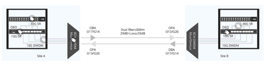
In this DWDM solution, in order to extend 40G QSFP+ connection distance, one 40G SR4 QSFP+ transceiver installed on the 40G switch is linked with four 10G SR transceivers by MTP-LC harness cables. In this way, one 40G optical signal can be divided into four 10G signals, and then OEO (Optical- Electrical- Optical) converts them to the corresponding DWDM wavelengths to four 80km 10G DWDM SFP+ modules. Then, connect 10G DWDM SFP+ modules on the OEO repeater and DWDM Mux/Demux by using LC duplex patch cables. In the next step, the 8ch DWDM Mux/Demux will combine the four 10G DWDM signals of different wavelengths into one single fiber and the signal after multiplexing is transmitted through dark fiber. In this way, 40G QSFP+ distance can be extended up to 80km with the use of DCM (Dispersion Compensation Module), BA (Booster Amplifier) and PA (Pre-Amplifier).
Why This DWDM Solution?
Of course, we can't only look at the present design, but also have to make long-term plans, thinking about the future needs of customers.
Meet Demands for Expansion
DWDM Mux/Demux can combine 10G signals of different wavelengths on one single fiber, which is the best solution to increase network capacity and save cost. In this DWDM solution, we choose the 8ch DWDM Mux/Demux instead of 4ch, because 8ch DWDM Mux/Demux can provide customers with later expansion. These two sites is a 40G point to point link, which can fully realize two 40G dual fiber connection up to 80km with 8ch.
Low Link Loss
In order to ensure the quality of signal, it is necessary to control the single-wave output power of BA (Booster Amplifier) below +8 dB, and the single-wave input power of PA (Pre- Amplifier) is controlled above -25 dB. DWDM solution is suitable for the point to point link whose link loss is from 29 to 33 dB. When the link loss reaches the maximum value of 33 dB, there is still a margin of 3 dB.
FAQs
Q: How to put OBA and OPA?
Optical Booster Amplifier (OBA) should be put behind the optical transmitter MUX while in front of the optical fiber line, which can increase the power of the transmitted light. And in order to amplify the weak optical signal, the Optical Pre-Amplifier (OPA) should be placed before the optical receiver Mux but after the optical fiber line.
Q: Why do we use OEO?
OEO is an optical media converter which allows connection between fiber-to-fiber Ethernet equipment, serving as fiber mode converter, or as fiber repeater for long-distance transmission. In this DWDM solution, we need OEO to convert common 10G signals to the corresponding DWDM wavelengths, so that they can transmit in the DWDM Mux/Demux.

Conclusion
DWDM solution provides a good way to solve the distance problem, making 40 km transmission distance is not the limit of 40G connection anymore. If you want to know more information, please reach us via [email protected].
0 notes
Text
Optical Transport Network (OTN) Market Emerging Trends and Competitive Landscape Forecast To 2025
Global Optical Transport Network (OTN) Market is expected to grow from US$ 11.70 billion in 2016 to US$ 33.44 billion by 2025 at a CAGR of 12.45% between 2016 and 2025
Get PDF Sample Copy@ http://bit.ly/2UFSOdu Optical Transport Network (OTN) is a next generation industry protocol that facilitates a globally standardized and optimized way to multiplex varied services on the optical light paths. The OTN encases every individual client’s payloads transparently in a container in order to transmute it across optical networks, conserving client’s native structure, management information and timing information. OTN-based metro cores and backbones provides noteworthy benefits over customary WDM transponder-based networks, including increased efficiency, reliability, and wavelength based private services.

0 notes
Text
2 Ports QSFP to QSFP 40G WDM Transponder OEO Converter w/full 3R Support Standalone
2 Ports QSFP to QSFP 40G WDM Transponder OEO Converter w/full 3R Support Standalone

FM SKU#:SKU000001G2 Model#:2P-40G-3R-Q-FMOEO MFG PART#:
QSFP to QSFP 40G WDM Transponder OEO Converter comes with two QSFP ports, are Standalone device that can support the “Three Rs” to Retime,Regenerate and Reshape the optical signal.
Transponders are fiber-to-fiber media converters that convert wavelengths for Wavelength Division Multiplexing (WDM) applications.
Fiber-Mart transponders are…
View On WordPress
0 notes
Text
Analysis of OEO Transponder Application in WDM Network
Anyone who has experiences of deploying WDM networks, either DWDM or CWDM networks, may be familiar with OEO transponder. Since in WDM network deployment, especially for long haul transmission, OEO transponder plays an important role. OEO transponder, also known as WDM transponder, means optical-to-electrical-to-optical. That is to say, it converts an optical signal to an electrical signal, and then recovers it to an optical signal. In some cases, OEO transponder serves as fiber mode converter or repeater for long distance transmission.
Functions of OEO Transponder
Wavelength Conversion
As we all know, when add a CWDM Mux/Demux or DWDM Mux/Demux into a WDM network, there is a requirement to convert the optical wavelengths like 850nm, 1310nm and 1550nm to CWDM or DWDM wavelengths. Then the OEO transponder comes to assist. The OEO transponder receives, amplifies and re-transmits the signal on a different wavelength without changing the signal content.
Fiber Mode Conversion
It’s know to us that multimode fiber optic cables (MMF) are often used in short distance transmission, while single mode fiber optic cables (SMF) are applied in long optical transmission. Therefore, in some network deployment, considering the transmission distances, MMF to SMF or SMF to MMF conversions are needed.
Signal Repeating
In long haul fiber optic transmission, OEO transponder also can work as repeater to extend network distance by converting wavelengths (1310nm to 1550nm) and amplifying optical power. The OEO converter converts the weak optical signals from the fiber into electrical signals, and regenerates or amplifies, then recovers them into strong optical signals for continuous transmission.
Analysis of OEO Transponder Application Case
Having known about the function of OEO transponder, here let me take some application cases as examples to illustrate its applications clearly.
Case One
The distance between site A and site B is about 165km, and there is a repeater station C. The distance between A and C is 90km. The client needs to build connection between A and B. Just like the following picture shows.
In this solution, three OEO transponders are used in this links according to the requirements of the client. The use of the first OEO converter at site A is to convert the signals from MMF to SMF, achieving the long distance transmission between site A and C. The second OEO transponder re-generates and amplifies the optical signal, then convert the it from dual fiber to single fiber. At site B, the OEO transponder re-amplifies the optical signal and recovers it to multimode transmission.
Advantages of this solution: use OEO transponder to achieve fiber mode conversion and long distance transmission; make full use of the OEO transponder (retime, regenerate and reshape) to realize high quality connections; save cost by using the OEO transponder.
Case Two
This solution is more complicated than the first one. There are three sites with fiber links between them. The distance between site A and B is 84km, and site B and C is 1km. Site A and C is 84km too. All the 10G connections are dual fiber transmission. Here is a simple picture of this solution.
As we can see in the figure, to build DWDM networks between these three sites, six OEO transponders are deployed. Each site uses two OEO transponders. The OEO transponder at site A converts the 10G-LR signals into 10G DWDM wavelengths, then the wavelengths are multiplexed by the DWDM Mux. At site B, the separated wavelengths are recovered to 10G-LR signals through the OEO transponder. The transmission between site B and C, site A and C are similar to the transmission between site A and B. In addition, there are two EDFAs in each two long distance transmissions.
Advantages of this solution: using OEO transponder for wavelength conversion. Converting common 10G signals into DWDM wavelengths and transmitting them with DWDM MUX/DEMUX increase the network capacity easily. At the same time, it also reduces the damage of optical transceivers.
Summary
OEO transponder is an important components in optical networks. This post gives a simple analysis of OEO transponder application case. Hope it’s useful for you. FS.COM supplies high quality 10G OEO converters like SFP+ to SPF+ and XFP to XFP, and 40G WDM transponder like QSFP+ to QSFP+. If you want to know more detailed information, please contact us.
Sources:http://www.fiber-optic-components.com/analysis-of-oeo-…n-in-wdm-network.html
0 notes
Text
10G C/DWDM Transponder
https://www.optical-sintai.com/products/10g-dwdm-transponder.html
10G OTU service card launched by Sintai Communication Co., Ltd. supports four types of service access with 42M~11.3G rates.
Its main function is to finish the 3R regeneration of any 4-channel signals under any protocol within the rate of 1.25 Gbit/s~11.3 Gbit/s to be accessed, and then convert them to optical signals of a standard DWDM wavelength or standard CWDM wavelength, so that the multiplexing unit can conduct WDM for optical signals of different wavelengths and also achieve the inverse process of the above process.
It's applicable to the wavelength division transmission solution for any access of services with the rate of 11.3G or below.
10G C/DWDM Transponder Specification
Function
Note
Card type
10G OTU-3R
10G OTU-2R
interface
·
Client-side interface: 4 SFP+ hot-pluggable, compatible with SFP
·
·
WDM-side interface: 4 SFP+ hot-pluggable, compatible with SFP
·
Line mode
Supports transparent transmission of any type of service in four 42M~11.3G rate ranges, and converts four service optical signals into four WDM standard wavelength optical signals.
Relay mode
Support 42M~11.3G wavelength electrical relay.
Support service type
GE, 10GE
1/2/4/8/10G FC
STM-16/64
CPRI-2/3/6/7
FE, GE, 10GE
1/2/4/8/10G FC
STM-1/4/16/64, OTU1/OTU2/OTU2e
CPRI-1~8, 42M~11.3G Any
WDM technology
·
Support CWDM: 18 waves
·
·
Support DWDM: C band 50GHz 96 waves
·
Occupied slot number
Support OTNS8600 series chassis, occupy 1 slot.
Network management function
Support real-time monitoring of the port working state, including transmitting optical power and receiving optical power, temperature, etc.
Power consumption
16W (max, including transceiver)
MTBF
>100000 hours

0 notes
Text
Optical Transponder Market Future | Significant Trends & Status | Forecast To 2028
Optical Transponder Market is estimated to witness substantial growth in the forecast period due to high adoption of optical wireless DAS (distributed antenna system). A transponder or (optical-electrical-optical) OEO is a device that sends and receives optical signal from a fiber. It is typically known by its data rate and determining maximum distance the signal can travel. A transponder is capable of converting optical and electrical signals, serialization and deserialization, monitoring and controlling. They test compatibility and interoperability including receiver sensitivity, function of (BER) bit of error, jitter performance, and transmission performance.
Optical transponders market is driven by increase in preference of copper wires to optic fibres, growing need for improved network bandwidth, high acceptance of optical wireless DAS, growing number of FTTx (Fiber To The x) connections, and explosive traffic of the internet. DAS (distributed antenna system) offers better indoor network coverage for the growing wireless traffic of the internet. Here, DAS counters low signal jamming that exceeds the available bandwidth. FTTx reduces installation price of high bandwidth services at home. FTTH (Fiber To The Home) replaces copper, cable, or telephone wires with fiber optic cable for high speed services.
Request Sample Copy of this Market Research @ https://www.millioninsights.com/industry-reports/optical-transponder-market/request-sample
Market Segment:
Report contents include
• Analysis of the optical transponder market including revenues, future growth, market outlook
• Historical data and forecast
• Regional analysis including growth estimates
• Analyzes the end user markets including growth estimates.
• Profiles on optical transponder including products, sales/revenues, and market position
• Market structure, market drivers and restraints.
Key regions
• North America
• Europe
• Asia Pacific
• Middle East and Africa
• South America
Browse Complete Report with TOC @ https://www.millioninsights.com/industry-reports/optical-transponder-market
Emergence of new telecommunication standards like 4G and 5G is stimulating customers to adopt higher bandwidth services and applications. Hence, large enterprises are opting cloud services like Google Apps, Microsoft Office 365, and SAP. Moreover, advantages of optic fibres, such as cost-effectiveness, lightweight, non-flammability, and transmission of higher bandwidth is driving the optical transponder industry.
Shifting trend of (OTNs) Optical Transport Network towards (WDM) Wavelength-Division Multiplexing architecture is an emerging trend in the optical transponder market. Nonetheless, different architecture requirements from various applications is a challenge for the market.
Optical transponder industry is categorized on the basis of transponder type, application, and geography. On the basis of transponder type, the market is divided into 155 Mbps, 2.5 Gbps, and 10 Gbps. 2.5 Gpbs segment is predicted to lead the market owing to wide range of service types from 155 Mbps to 2.5 Gbps. It includes services, such as SONET OC-3 through OC-48, ESCON, Gigabit Ethernet, SDH STM-1 through STM-16, 1- or 2-Gbps Fibre Channel, and other services.
In terms of application, optical transponders market is split into data transmission network, broadband campus network, enterprise network, computer data transmission network, and cable television. Data transmission network and computer data transmission network segment lead the optical transponder industry in the forecast period due to rapid industrialization and high demand from Datacom industry.
Geographically, optical transponder market is segmented as North America, South America, Europe, Asia Pacific, and Middle East & Africa. Asia Pacific is expected to dominate the market in the coming years due to increase in disposable income of consumers and change in standard of living. Furthermore, North America and South America contribute significantly to the market.
The major players in optical transponders industry are Hitachi Metals, OpLink, Fujitsu, Oclaro, JDSU, Hioso, Sumitomo, Bricom, Avago, Source Photonics, Wantong, Huahuan, Emcore, CMR, WTD, Finisar, Green Well, Ruby Tech, and NeoPhotonics.
For More Information, Visit Our Blog @ www.digitalmarket360.wordpress.com
0 notes
Text
Optical Transponder Market Outlook to 2023: Top Manufacturer Analysis, Industry Overview and Forecast Report
01st July 2019 – Global Optical Transponder Market is estimated to witness substantial growth in the forecast period due to high adoption of optical wireless DAS (distributed antenna system). A transponder or (optical-electrical-optical) OEO is a device that sends and receives optical signal from a fiber. It is typically known by its data rate and determining maximum distance the signal can travel. A transponder is capable of converting optical and electrical signals, serialization and deserialization, monitoring and controlling. They test compatibility and interoperability including receiver sensitivity, function of (BER) bit of error, jitter performance, and transmission performance.
Optical transponders market is driven by increase in preference of copper wires to optic fibres, growing need for improved network bandwidth, high acceptance of optical wireless DAS, growing number of FTTx (Fiber To The x) connections, and explosive traffic of the internet. DAS (distributed antenna system) offers better indoor network coverage for the growing wireless traffic of the internet. Here, DAS counters low signal jamming that exceeds the available bandwidth. FTTx reduces installation price of high bandwidth services at home. FTTH (Fiber To The Home) replaces copper, cable, or telephone wires with fiber optic cable for high speed services.
Access Optical Transponder Market Report with TOC
Emergence of new telecommunication standards like 4G and 5G is stimulating customers to adopt higher bandwidth services and applications. Hence, large enterprises are opting cloud services like Google Apps, Microsoft Office 365, and SAP. Moreover, advantages of optic fibres, such as cost-effectiveness, lightweight, non-flammability, and transmission of higher bandwidth is driving the optical transponder industry.
Shifting trend of (OTNs) Optical Transport Network towards (WDM) Wavelength-Division Multiplexing architecture is an emerging trend in the optical transponder market. Nonetheless, different architecture requirements from various applications is a challenge for the market.
Optical transponder industry is categorized on the basis of transponder type, application, and geography. On the basis of transponder type, the market is divided into 155 Mbps, 2.5 Gbps, and 10 Gbps. 2.5 Gpbs segment is predicted to lead the market owing to wide range of service types from 155 Mbps to 2.5 Gbps. It includes services, such as SONET OC-3 through OC-48, ESCON, Gigabit Ethernet, SDH STM-1 through STM-16, 1- or 2-Gbps Fibre Channel, and other services.
The major players in optical transponders industry are Hitachi Metals, OpLink, Fujitsu, Oclaro, JDSU, Hioso, Sumitomo, Bricom, Avago, Source Photonics, Wantong, Huahuan, Emcore, CMR, WTD, Finisar, Green Well, Ruby Tech, and NeoPhotonics.
Request a Sample Copy of Optical Transponder Market Report
In terms of application, optical transponders market is split into data transmission network, broadband campus network, enterprise network, computer data transmission network, and cable television. Data transmission network and computer data transmission network segment lead the optical transponder industry in the forecast period due to rapid industrialization and high demand from Datacom industry.
Geographically, optical transponder market is segmented as North America, South America, Europe, Asia Pacific, and Middle East & Africa. Asia Pacific is expected to dominate the market in the coming years due to increase in disposable income of consumers and change in standard of living. Furthermore, North America and South America contribute significantly to the market.
0 notes
Text
Do you know Fiber Optical Transponders?
by www.fiber-mart.com
What is
Fiber Optical Transponder
? As we know, transponder is important in optical fiber communications, it is the element that sends and receives the optical signal from a fiber. A transponder is typically characterized by its data and the maximum distance the signal can travel. Functions of a Fiber Optical Transponder includes: Electrical and optical signals conversionSerialzation and deserializationControl and monitoringApplications of Fiber Optical Transponder Multi-rate, bidirectional fiber transponders convert short-reach 10gb/s and 40 gb/s optical signals to long-reach, single-mode dense wavelength division multiplexing (DWDM) optical interfaces. The modules can be used to enable DWDM applications such as fiber relief, wavelength services, and Metro optical DWDM access overtay on existing optical infrastructure. Supporting dense wavelength multiplexing schemes, fiber optic transponders can expand the useable bandwidth of a single optical fiber to over 300 Gb/s. Transponders also provide a standard line interface for multiple protocols through replaceable 10G small form-factor pluggable (XFP) client-side optics. The data rate and typical protocols transported include synchronous optical network/synchronous digital hierarchy (SONET/SDH) (OC-192 SR1), Gigabit Ethernet (10GBaseS and 10GBaseL), 10G Fibre Channel (10 GFC) and SONET G.709 forward error correction (FEC)(10.709 Gb/s). Fiber optic transponder modules can also support 3R operation (reshape, retime, regenerate) at supported rates. Often, fiber optic transponders are used to for testing interoperability and compatibility. Typical tests and measurements include litter performance, receiver sensitivity as a function of bit error rate (BER), and transmission performance based on path penalty.Some fiber optic transponders are also used to perform transmitter eye measurements. fiber-mart.com Provides Optical Transponders Solution Let’s image that the architecture that can not support automated reconfigureability. Connectivity is provided via a manual Fibre Optic Patch Panel, a patch panel where equipment within an office is connected via fiber cables to one side (typically in the back), and where short patch cables are used on the other side (typically in the front) to manually interconnect the equipment as desired. There is a point that Fibre Optic Patch Panel, people usually different ports patch panel , for example, 6, 8, 12, 24 port fiber patch panel and they according to different connectors to choose different patch panel, such as LC patch panel, LC patch panel, MTP patch panel… The traffic that is being added to or dropped from the optical layer at this node is termed add/drop traffic, the traffic that is transmitting the mode is called through traffic. Regardless of the traffic type, note that all of the traffic entering and exiting the node is processed by a WDM transponder. In the course of converting between a WDM-compatible optical signal and a client optical signal, the transponder processes the signal in the electrical domain. Thus, all traffic enters the node in the optical domain, is converted to the electrical domain, and is returned to the optical domain. This architecture, where all traffic undergoes optical electrical (OEO) conversion, is referred to as the OEO architecture.
0 notes
Text
Fundamentals of Communications Access Technologies: FDMA, TDMA, CDMA, OFDMA, AND SDMA | Soukacatv.com
An introduction to the access technologies that allow multiple users to share a common communications channel.
Access methods are multiplexing techniques that provide communications services to multiple users in a single-bandwidth wired or wireless medium. Communications channels, whether they’re wireless spectrum segments or cable connections, are expensive. Communications services providers must engage multiple paid users over limited resources to make a profit. Access methods allow many users to share these limited channels to provide the economy of scale necessary for a successful communications business. There are five basic access or multiplexing methods: frequency division multiple access (FDMA), time division multiple access (TDMA), code division multiple access (CDMA), orthogonal frequency division multiple access (OFDMA), and spatial division multiple access (SDMA).
HDMI Encoder Modulator,16in1 Digital Headend, HD RF Modulator at Soukacatv.com
SKD3013 3 Channel HD Encode Modulator
SKD121X Encoding & Multiplexing Modulator
Household Universal Encoding & Modulation Modulator
SKD19 Series 1U Rack 12CH Encode Modulator
FDMA
FDMA is the process of dividing one channel or bandwidth into multiple individual bands, each for use by a single user (Fig. 1). Each individual band or channel is wide enough to accommodate the signal spectra of the transmissions to be propagated. The data to be transmitted is modulated on to each subcarrier, and all of them are linearly mixed together.
1. FDMA divides the shared medium bandwidth into individual channels. Subcarriers modulated by the information to be transmitted occupy each subchannel.
The best example of this is the cable television system. The medium is a single coax cable that is used to broadcast hundreds of channels of video/audio programming to homes. The coax cable has a useful bandwidth from about 4 MHz to 1 GHz. This bandwidth is divided up into 6-MHz wide channels. Initially, one TV station or channel used a single 6-MHz band. But with digital techniques, multiple TV channels may share a single band today thanks to compression and multiplexing techniques used in each channel.
This technique is also used in fiber optic communications systems. A single fiber optic cable has enormous bandwidth that can be subdivided to provide FDMA. Different data or information sources are each assigned a different light frequency for transmission. Light generally isn’t referred to by frequency but by its wavelength (λ). As a result, fiber optic FDMA is called wavelength division multiple access (WDMA) or just wavelength division multiplexing (WDM).
One of the older FDMA systems is the original analog telephone system, which used a hierarchy of frequency multiplex techniques to put multiple telephone calls on single line. The analog 300-Hz to 3400-Hz voice signals were used to modulate subcarriers in 12 channels from 60 kHz to 108 kHz. Modulator/mixers created single sideband (SSB) signals, both upper and lower sidebands. These subcarriers were then further frequency multiplexed on subcarriers in the 312-kHz to 552-kHz range using the same modulation methods. At the receiving end of the system, the signals were sorted out and recovered with filters and demodulators.
Original aerospace telemetry systems used an FDMA system to accommodate multiple sensor data on a single radio channel. Early satellite systems shared individual 36-MHz bandwidth transponders in the 4-GHz to 6-GHz range with multiple voice, video, or data signals via FDMA. Today, all of these applications use TDMA digital techniques.
TDMA
TDMA is a digital technique that divides a single channel or band into time slots. Each time slot is used to transmit one byte or another digital segment of each signal in sequential serial data format. This technique works well with slow voice data signals, but it’s also useful for compressed video and other high-speed data.
A good example is the widely used T1 transmission system, which has been used for years in the telecom industry. T1 lines carry up to 24 individual voice telephone calls on a single line (Fig. 2). Each voice signal usually covers 300 Hz to 3000 Hz and is digitized at an 8-kHz rate, which is just a bit more than the minimal Nyquist rate of two times the highest-frequency component needed to retain all the analog content.
2. This T1 digital telephony frame illustrates TDM and TDMA. Each time slot is allocated to one user. The high data rate makes the user unaware of the lack of simultaneity.
The digitized voice appears as individual serial bytes that occur at a 64-kHz rate, and 24 of these bytes are interleaved, producing one T1 frame of data. The frame occurs at a 1.536-MHz rate (24 by 64 kHz) for a total of 192 bits. A single synchronizing bit is added for timing purposes for an overall data rate of 1.544 Mbits/s. At the receiving end, the individual voice bytes are recovered at the 64-kHz rate and passed through a digital-to-analog converter (DAC) that reproduces the analog voice.
The basic GSM (Global System of Mobile Communications) cellular phone system is TDMA-based. It divides up the radio spectrum into 200-kHz bands and then uses time division techniques to put eight voice calls into one channel. Figure 3 shows one frame of a GSM TDMA signal. The eight time slots can be voice signals or data such as texts or e-mails. The frame is transmitted at a 270-kbit/s rate using Gaussian minimum shift keying (GMSK), which is a form of frequency shift keying (FSK) modulation.
3. This GSM digital cellular method shows how up to eight users can share a 200-kHz channel in different time slots within a frame of 1248 bits.
CDMA
CDMA is another pure digital technique. It is also known as spread spectrum because it takes the digitized version of an analog signal and spreads it out over a wider bandwidth at a lower power level. This method is called direct sequence spread spectrum (DSSS) as well (Fig. 4). The digitized and compressed voice signal in serial data form is spread by processing it in an XOR circuit along with a chipping signal at a much higher frequency. In the cdma IS-95 standard, a 1.2288-Mbit/s chipping signal spreads the digitized compressed voice at 13 kbits/s.
4. Spread spectrum is the technique of CDMA. The compressed and digitized voice signal is processed in an XOR logic circuit along with a higher-frequency coded chipping signal. The result is that the digital voice is spread over a much wider bandwidth that can be shared with other users using different codes.
The chipping signal is derived from a pseudorandom code generator that assigns a unique code to each user of the channel. This code spreads the voice signal over a bandwidth of 1.25 MHz. The resulting signal is at a low power level and appears more like noise. Many such signals can occupy the same channel simultaneously. For example, using 64 unique chipping codes allows up to 64 users to occupy the same 1.25-MHz channel at the same time. At the receiver, a correlating circuit finds and identifies a specific caller’s code and recovers it.
The third generation (3G) cell-phone technology called wideband CDMA (WCDMA) uses a similar method with compressed voice and 3.84-Mbit/s chipping codes in a 5-MHz channel to allow multiple users to share the same band.
OFDMA
OFDMA is the access technique used in Long-Term Evolution (LTE) cellular systems to accommodate multiple users in a given bandwidth. Orthogonal frequency division multiplexing (OFDM) is a modulation method that divides a channel into multiple narrow orthogonal bands that are spaced so they don’t interfere with one another. Each band is divided into hundreds or even thousands of 15-kHz wide subcarriers.
The data to be transmitted is divided into many lower-speed bit streams and modulated onto the subcarriers. Time slots within each subchannel data stream are used to package the data to be transmitted (Fig. 5). This technique is very spectrally efficient, so it provides very high data rates. It also is less affected by multipath propagation effects.
5. OFDMA assigns a group of subcarriers to each user. The subcarriers are part of the large number of subcarriers used to implement OFDM for LTE. The data may be voice, video, or something else, and it’s assembled into time segments that are then transmitted over some of the assigned subcarriers.
To implement OFDMA, each user is assigned a group of subchannels and related time slots. The smallest group of subchannels assigned is 12 and called a resource block (RB). The system assigns the number of RBs to each user as needed.
SDMA
SDMA uses physical separation methods that permit the sharing of wireless channels. For instance, a single channel may be used simultaneously if the users are spaced far enough from one another to avoid interference. Known as frequency reuse, the method is widely used in cellular radio systems. Cell sites are spaced from one another to minimize interference.
In addition to spacing, directional antennas are used to avoid interference. Most cell sites use three antennas to create 120° sectors that allow frequency sharing (Fig. 6a). New technologies like smart antennas or adaptive arrays use dynamic beamforming to shrink signals into narrow beams that can be focused on specific users, excluding all others (Fig. 6b)
6. SDMA separates users on shared frequencies by isolating them with directional antennas. Most cell sites have three antenna arrays to separate their coverage into isolated 120° sectors (a). Adaptive arrays use beamforming to pinpoint desired users while ignoring any others on the same frequency (b).
One unique variation of SDMA, polarization division multiple access (PDMA), separates signals by using different polarizations of the antennas. Two different signals then can use the same frequency, one transmitting a vertically polarized signal and the other transmitting a horizontally polarized signal.
The signals won’t interfere with one another even if they’re on the same frequency because they’re orthogonal and the antennas won’t respond to the oppositely polarized signal. Separate vertical and horizontal receiver antennas are used to recover the two orthogonal signals. This technique is widely used in satellite systems.
Polarization is also used for multiplexing in fiber optic systems. The new 100-Gbit/s systems use dual polarization quadrature phase shift keying (DP-QPSK) to achieve high speeds on a single fiber. The high-speed data is divided into two slower data streams, one using vertical light polarization and the other horizontal light polarization. Polarization filters separate the two signals at the transmitter and receiver and merge them back into the high-speed stream.
Other Methods
A unique and widely used method of multiple access is carrier sense multiple access with collision detection (CSMA-CD). This is the classical access method used in Ethernet local-area networks (LANs). It allows multiple users of the network to access the single cable for transmission. All network nodes listen continuously. When they want to send data, they listen first and then transmit if no other signals are on the line. For instance, the transmission will be one packet or frame. Then the process repeats. If two or more transmissions occur simultaneously, a collision occurs. The network interface circuitry can detect a collision, and then the nodes will wait a random time before retransmitting.
A variation of this method is called carrier sense multiple access with collision avoidance (CSMA-CA). This method is similar to CSMA-CD. However, a special scheduling algorithm is used to determine the appropriate time to transmit over the shared channel. While the CSMA-CD technique is most used in wired networks, CSMA-CA is the preferred method in wireless networks.
Established in 2000, the Soukacatv.com main products are modulators both in analog and digital ones, amplifier and combiner. We are the very first one in manufacturing the headend system in China. Our 16 in 1 and 24 in 1 now are the most popular products all over the world.
For more, please access to https://www.soukacatv.com.
CONTACT US
Company:Dingshengwei Electronics Co., Ltd
Address : BldgA,the first industry park of Guanlong,Xili Town,Nanshan,Shenzhen,Guangdong,China
Tel : +86 0755 26909863
Fax : +86 0755 26984949
Mobile : 13410066011
Email : [email protected]
Source: electronicdesign
0 notes
Text
The Advantages of CATV EDFA
The Advantages of CATV EDFA

Optical amplifiers serve as an integrated part of long haul data transmission. Fiber optical transponders and fiber optical amplifier are used in the WDM fiber optic system, and it makes WDM transmission possible. In recent years,fiber optic CATV EDFA System especially 1500nm optical fiber CATV System is being rapidly develop in our country.
What is EDFA?
Erbium Doped Fiber Amplifier is short…
View On WordPress
0 notes
Text
The system structure of OTN equipment
Hi, everyone!
Today I'm going to introduce you about the system structure of Huawei OTN equipment
The OTN device mainly contains five parts, they are OTU(Optical Transponder Unit), XCS(Cross-connection Unit), OMU/ODU(Optical Multiplex Unit/Optical Demultiplex Unit), OA(Optical Amplifier) and OSC/ESC(Optical/Electrical Supervisory Channel).
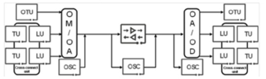
The OUT boards convert the non-standard wavelength into the standard wavelength specified by the ITU-T. The system uses the optical/electrical/optical (O/E/O) conversion. That is the received optical signal is converted into the electrical signal by using the photodiode PIN or APD, and then the electrical signal modulates the laser of the standard wavelength, in this way, a new optical wavelength signal that meets requirements is obtained.
The XCS boards receive data from service boards (line boards and tributary boards), cross-connects ODUk(k=0, 1, 2, 2e, 3, 4, flex)/VC-4 service signals at the electrical layer, and then transmits the signals to service boards for service cross-connection.
The OMU boards ware used at the transmit end. Each input port of the OMU boards inputs one pre-selected wavelength of optical signals, and the input wavelengths are output through the same output port. The ODU boards are used at the receiving end. They have one input port and multiple output ports to classify signals of different wavelengths.
The OA boards can directly amplify optical signals and provide real-time, high-gain, broadband, online, low-noise, and low-loss all-optical amplifiers. Currently, EDFAs and FRAs are commonly used, erbium-doped fiber amplifiers (EDFAs) are widely used as preamplifiers, line amplifiers and power amplifiers in long-distance, large-capacity, and high-speed fiber communication systems.
The OSC/ESC boards are used to monitor the WDM optical transmission system. ITU-T recommends that you use the 1510 nm wavelength with a capacity of 2Mbit/s. The receiver sensitivity (better than –48dBm) is normal when the rate is low. The optical signals must be dropped before the EDFA and added after the EDFA.
0 notes